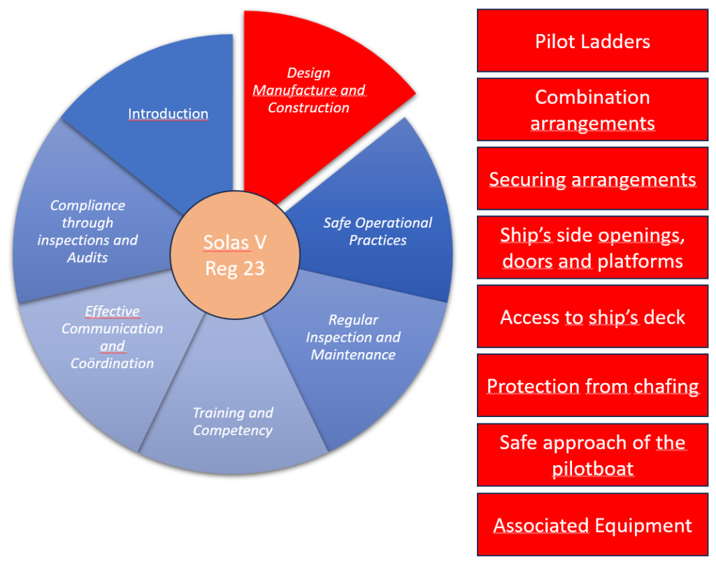
4 Pilot ladders
4.1 The steps of the pilot ladders shall comply with the following requirements:
.1 if made of hardwood, they shall be made in one piece, free of any knots. Wood shall not be treated or coated with paint, varnish or other coatings;
.2 if made of material other than hardwood, they shall be made from resilient plastic or rubber of equivalent strength, stiffness and durability;
.3 the four lowest steps shall be of rubber of sufficient strength and stiffness or other equivalent material;
.4 they shall have an efficient non-slip surface;
.5 they shall be long enough to accommodate a distance between the inner surface of the side ropes of not less than 400 mm, and shall be 115 mm in width and 25 mm in depth, excluding any non-slip device or grooving;
.6 they shall be equally spaced not less than 310 mm and not more than 350 mm apart measured from the top of each step or spreader step; and
.7 they shall be secured in such a manner that each will remain horizontal.
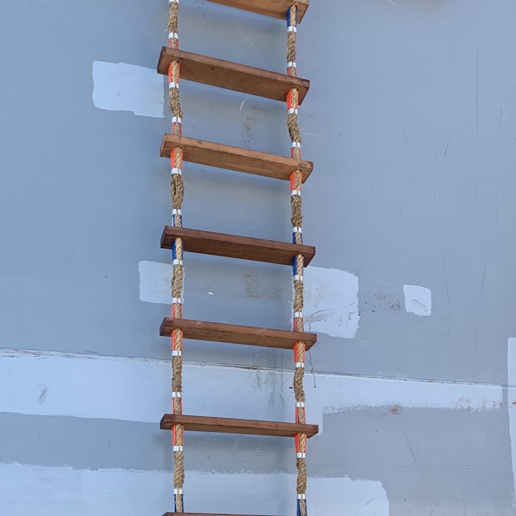
4.2 Pilot ladders with more than five steps shall have spreader steps complying with paragraph 4.1 and each spreader step shall be not less than 1.8 m in length. The lowest spreader step shall be the fifth step from the bottom of the ladder and additional spreader steps shall be provided at such intervals as will prevent the pilot ladder from twisting conforming to standards accepted by the Organization[1].
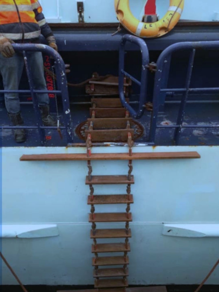
4.3 Permanent measuring marking shall be provided at a regular interval of every three steps (approximately every 1 m) throughout the length of the pilot ladder consistent with ladder design, use and maintenance in order to facilitate the rigging of the ladder to the required height.
4.4 Pilot ladders shall be permanently marked by the manufacturer with at least the following information on the underside of the uppermost step and the lowermost spreader step:
.1 the name of the manufacturer;
.2 an equipment serial number or other means of unique identification which the manufacturer shall be able to validate;
.3 date of manufacture; and
.4 name and details of the approving authority.

The inclusion of Article 4.4 in the SOLAS regulations is a welcome development in combating the persistent trade of counterfeit and non-approved pilot ladders. In recent years, there has been an alarming increase in the sale of secondhand and substandard pilot ladders, posing significant risks to maritime safety. To address this issue, it is crucial that pilot ladders are properly marked as outlined in the regulations. Additionally, a valid certificate for the pilot ladders in use on board should be readily accessible to ensure compliance and safety.
4.5 Pilot ladders shall be of a single length capable of reaching the surface of the water from the point of access or, where a combination arrangement is used, from the platform of the combination arrangement, in all seagoing conditions of draught and trim and the specific condition of an adverse list of 15° in the lightest seagoing condition.
4.6 The side ropes on each side of the pilot ladder should consist of a double length of uncovered rope not less than 20 mm and not more than 22 mm in diameter. The double length shall be made from a continuous length of rope with no joints having a breaking strength of at least 24 kN. The midpoint of the double length shall be located on a thimble. The ends of each side rope shall be properly finished.[2]
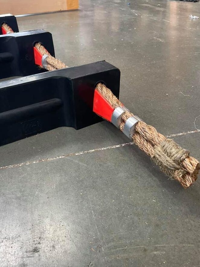
Do not cover the ends of the ropes at the bottom of pilot ladders with electrical tape, rubber, or duct tape—a practice observed all too frequently. Such coverings trap moisture, causing the rope ends to remain wet and eventually rot. For safety and durability, all ropework on the ladder should remain uncovered, allowing the ropes to dry properly in open air.
4.7 Each side rope shall be mildew-resistant manila rope[3] or other material of equivalent strength, durability, elongation characteristics and grip which has been protected against actinic degradation.
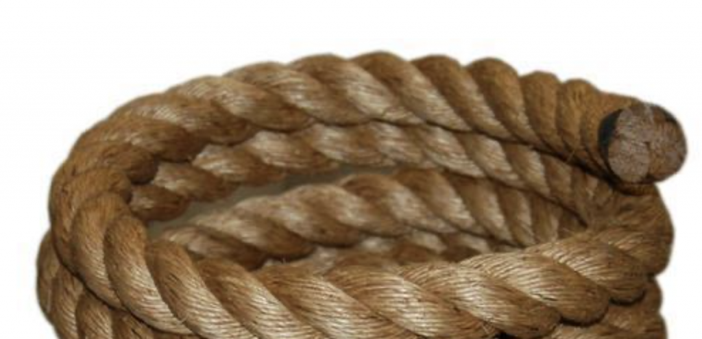
Sometimes issues arise when substandard materials, such as sisal ropes, are found on low-quality pilot ladders. Sisal ropes do not meet the necessary standards for strength, durability, or resistance to environmental degradation. Acceptable alternatives to manila ropes include polyester ropes or other synthetic materials, provided they meet the following criteria:
- Breaking Strength: Equivalent to or greater than the minimum breaking strength required for manila ropes in this application. (24kN)
- Durability and Grip: The material must offer comparable durability and grip under operational conditions.
- Resistance to Degradation: The ropes must be resistant to actinic (UV) degradation and mildew.
It is essential to verify the specifications of ladder ropes, ensuring they conform to the breaking strength requirements and other safety parameters outlined in SOLAS regulations.
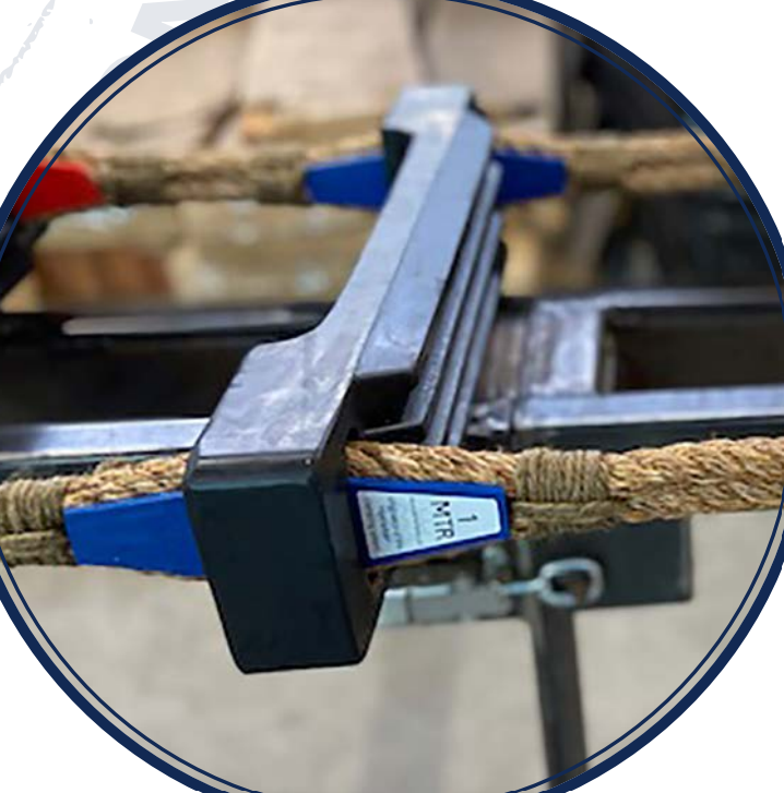
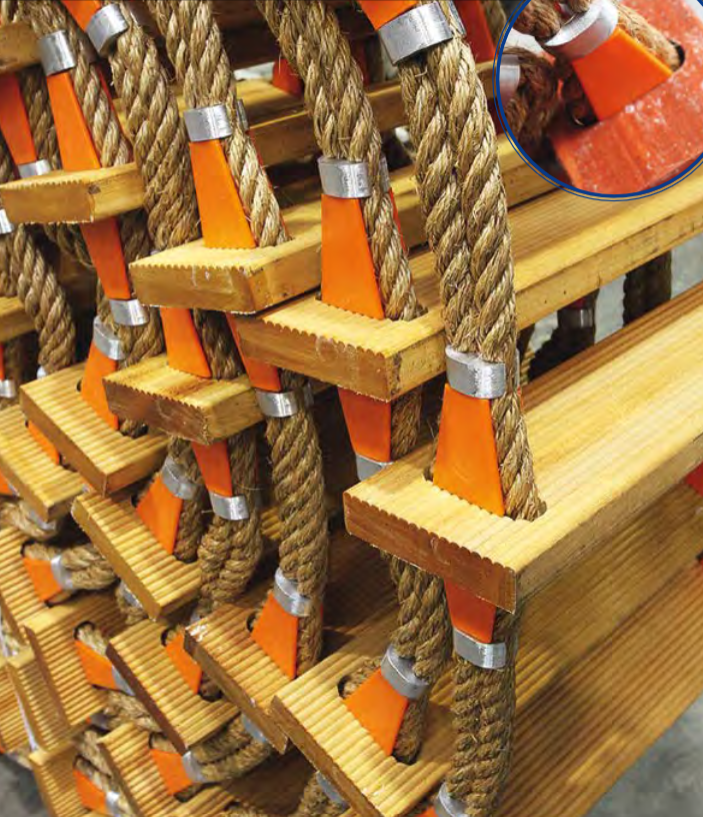
4.8 Each side ropes shall be secured together both above and below each step with an arrangement properly designed for this purpose. Where a seizing method[4] with step fixtures (chocks or wedges) is used, it shall hold each step horizontal in all planes at all times. Where a mechanical clamping device is used to secure each side rope together, it shall grip each side rope in the pair independently and with the same grip force. Any surface of a mechanical clamping device that pilots or other personnel may handle shall be suitable to be grasped by bare hands. The use of cable ties, u-clamps, worm driven clips as a means of securing steps within with side ropes is prohibited.
5 Combination arrangements
5.1 The length of the accommodation ladder shall be sufficient to ensure that its angle of slope does not exceed 45°. In ships with large draught ranges, several pilot ladder hanging positions shall be provided, resulting in lesser angles of slope. The accommodation ladder shall be at least 600 mm in width. The accommodation ladder hoisting and lowering mechanism includes protection that ensures the mechanism cannot be inadvertently operated during the transfer of pilots and other personnel.
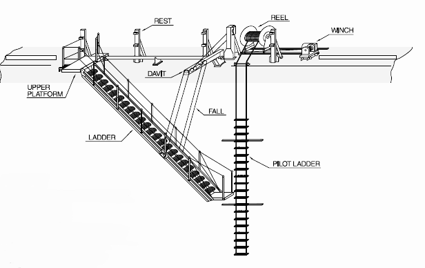
5.2 Intermediate platforms, if fitted, shall be self-levelling. Treads and steps of the accommodation ladder shall be so designed that an adequate and safe anti-skid foothold is given at the operative angles.
5.3 The accommodation ladder and platform shall be equipped on both sides with stanchions and rigid handrails, but if hand ropes are used, they shall be tight and properly secured. The vertical space between the handrail or hand rope and the stringers of the ladder shall be securely fenced.
5.4 Accommodation ladders, together with any suspension arrangements or attachments fitted and intended for use in accordance with these performance standards, shall meet the requirements for the means of embarkation on and disembarkation from ships as required by regulation II-1/3-9.
5.5 In the case of a combination arrangement using an accommodation ladder with a trapdoor in the lower platform, the lower platform shall:
.1 have an aperture with dimensions not less than 750 mm x 750 mm which is open to the ship’s hull on the inboard side and which is designed to ensure that the horizontal distance between the pilot ladder and adjacent edges of the aperture is between 0.1 and 0.2 m;
.2 be designed and constructed to:
.1 allow the pilot ladder and manropes to pass through the aperture without obstruction or distortion;
.2 ensure the pilot ladder lies flat against the ship’s side;
.3 ensure that structural members shall not interfere with or lay against the pilot ladders; and
.4 ensure the highest step of the pilot ladder is at least 2 m above the lower platform and remain compliant with part B;
.3 not be provided with fixtures other than the frame referred to in paragraph 5.5.7, which allows a pilot ladder to be suspended from the lower platform of the accommodation ladder;
.4 have a trapdoor which opens upwards and which is secured flat on the embarkation platform or against a stanchion either at the aft end or outboard side of the platform, and in any case not obstructing the access the ship;
.5 be provided with sufficient round handholds with a diameter of no less than 28 mm and not more than 32 mm to allow safe mounting or dismounting of the pilot ladder. The structure of the platform itself shall not be relied upon to provide handholds;
.6 be provided with sufficient handholds with a height of not less than 1.2 m above the platform;
.7 where a structural frame is used to comply with paragraph 5.5.2, the following shall apply:
.1 the accommodation ladder platform, frame, pilot ladder connection points, accommodation ladder winch, running gear, pad eyes of manropes and locking arrangements shall be designed to withstand vertical forces of at least 48 kN;
.2 the highest step of the pilot ladder is at least 2 m above the platform and is secured to pad eyes on the inboard side of the frame so that it rests firmly against the side of the ship; and
.3 manropes are secured directly to additional pad eyes 2 m above the platform on the inboard side of the frame.
5.6 On all ships to which section 5 applies, a two-tone visual mark, the upper half being white and the lower half being red, not less than 4 m in height and 0.5 m in width shall be provided in the midship half-length of the ship in the vicinity of the pilot boarding position to indicate to the user whether or not a combination arrangement should be rigged. The dividing line between the upper and the lower halves of the pilot line shall be 9 m below the point access.
6 Securing arrangements
6.1 All strong points, shackles and securing ropes provided or used in accordance with part A or part B shall have a breaking strength of not less than 48 kN. Securing ropes, if used to aid in rigging the pilot ladder, shall be at least 3 m in length. The securing arrangements shall be positioned not less than 915 mm, or, if not possible, the maximum permitted by the width of the deck, from the edge of the deck, except for the case of a combination arrangement using an accommodation ladder. Strong points and shackles shall have breaking strength or equivalent safe working load limits clearly and permanently marked. Documentation of the conformance of the strong points, shackles and securing ropes shall be maintained on board and available for inspection purposes.
6.2 Permanent or removable means of bowsing a pilot ladder or embarkation platform to the ship’s hull shall not be used to support the weight of the boarding arrangement or pilot and shall not be used for any other purpose than to secure the arrangement against the ship’s side. Removable means of bowsing a pilot ladder or embarkation platform to the ship’s side shall be able to be applied and removed by a single person and shall have a holding force of not less than 4 kN when used for the purpose of securing the lower platform of an accommodation ladder or 3 kN when used for securing the pilot ladder or manropes.[5]
6.3 There shall be a means of securing a pilot ladder at intermediate lengths which shall be capable of securing the pilot ladder to strong points described in paragraph 6.1 by gripping each set of side ropes of the pilot ladder. The means of securing, shall have a breaking strength of not less than 48 kN and be designed to prevent any slippage of the side ropes under the conditions of the ladder and step attachment strength test and unrolling tests described in a standard acceptable to the Organization.7[6] When type approving means of securing a pilot ladder at intermediate lengths in accordance with Part F, these tests shall be modified to reflect the attachment of the pilot ladder using a means of securing the pilot ladder other than using its own attachments.
7 Ship’s side openings, doors and platforms
7.1 Ship’s side doors used for the transfer of pilots or other personnel shall not open outwards unless located below the freeboard deck.[7] The side opening shall enable a safe, convenient and unobstructed passage large enough for the transfer of pilots and other personnel, with a minimum clearance of 2,200 mm in height and 915 mm in width.
7.2 Ship’s side openings without a boarding platform shall be provided with strong points which are on the lowest deck of the opening and inboard of the ship’s side opening. Strong points shall also be provided on the deck head and inboard of the ship side opening if it is intended to rig manropes in the manner provided for in paragraph 15.1.3.
7.3 Boarding platforms deployed from ship’s side openings and outboard of the ship in any event shall not be provided where the distance from the platform to the surface of the water in all seagoing conditions of draught and trim associated with the normal operation of the ship is less than 5 m. Platforms shall be mechanically attached to the ship and be marked with safe working load limits. Certification of successful testing shall be maintained on board and available for inspection.
7.4 The boarding platform shall extend outboard from the ship’s side for a minimum distance of 750 mm, with a longitudinal length of a minimum of 750 mm. The platform shall be securely guarded by handrails.
8 Access to ship’s deck
Means shall be provided to ensure safe, convenient and unobstructed passage for any person embarking on, or disembarking from, the ship between the head of the pilot ladder, or of any accommodation ladder, and the ship’s deck; such access shall be gained directly by a clean and unobstructed platform securely guarded by handrails. Where such passage is by means of:
.1 a gateway in the rails or bulwark, adequate handholds with a diameter of not less than 32 mm and not more than 36 mm shall be provided at the point of embarking on or disembarking from the ship on each side which shall be not less than 0.7 m and not more than 0.8 m apart in clear width. Each handhold shall be rigidly secured and locked to the ship’s structure at or near its base and also at a higher point, and shall extend not less than 1.2 m above the deck to which it is fitted. Stanchions or handrails of the gateway shall not be attached to the bulwark ladder to prevent the bulwark ladder from overturning and shall be positioned no greater than 0.12 m inboard of the edge of the deck. A ring or eye with an inner diameter not less than 60 mm at a height of the stanchion above the deck shall be provided to accommodate manropes;
.2 a bulwark ladder, it shall be securely attached to the ship to prevent overturning. Two separate handhold stanchions with a diameter of not less than 32 mm and not more than 36 mm shall be fitted at the point of embarking on or disembarking from the ship on each side which shall be not less than 0.7 m and not more than 0.8 m apart in clear width. Each stanchion shall be rigidly secured and locked to the ship’s structure at or near its base and also at a higher point and shall extend not less than 1.2 m above the top of the bulwarks. Stanchions or handrails of the gateway shall not be attached to the bulwark ladder to prevent the bulwark from overturning and shall be positioned no greater than 0.12 m inboard of the edge of the deck. A ring or eye with an inner diameter not less than 60 mm at a height of the stanchion above the deck shall be provided to accommodate manropes; and
.3 a shipside opening or door, adequate handholds with a diameter of not less than 32 mm and not more than 36 mm shall be provided at the point of embarking on or disembarking from the ship on each side which shall be not less than 0.7 m and not more than 0.8m apart in clear width. Each handhold shall be rigidly secured and locked to the shipʹs structure at its base in two places and be locked into place to prevent dislodgement and shall extend not less than 1.2 m above the entry threshold. Stanchions or handrails shall be positioned no greater than 0.12 m inboard of the edge of the deck. A ring or eye with an inner diameter not less than 60 mm at a height of the stanchion above the deck shall be provided to accommodate manropes.
9 Protection from chafing
Regardless of the arrangement used, equipment and arrangements shall be designed and installed so that it is not possible for a pilot ladder side rope or manrope to make contact with any part of the ship’s hull or associated fixtures and fittings which could have the potential to cause sharp bends, chafing, abrasion, pinching or otherwise degrade their performance. Where contact is unavoidable, contact points shall be rounded to minimize chafing. The means of rounding could be a permanent fixture, such as a rounded pipe. Where it is not possible to round contact points owing to ship design, removable chafing pads or other temporary arrangements may be used. They shall be considered acceptable to the Administration, provided these arrangements do not prevent pre-use inspections, are removed after use and stowed in accordance with paragraph 23.
10 Safe approach of the pilot boat
Where rubbing bands or other constructional features prevent the safe approach of a pilot boat, these shall be cut back to provide at least 6 m of unobstructed ship’s side. Specialized offshore ships less than 90 m or other similar ships less than 90 m for which a 6 m gap in the rubbing bands would not be practicable, as determined by the Administration, may be exempted. In this case, other appropriate measures shall be taken to ensure that pilots and other personnel are able to embark and disembark safely.
11 Associated equipment
Manropes shall be:
.1 not less than 28 mm and not more than 32 mm in diameter and shall be mildew-resistant manila rope,[8] or other material of equivalent strength, durability, elongation characteristics and grip;
.2 of a single length free from splices and knots; and
.3 tagged or otherwise permanently marked by the manufacturer with at least the following information:
.1 the name of the manufacturer;
.2 an equipment serial number or other means of unique identification which the manufacturer shall be able to validate;
.3 date of manufacture; and
.4 name and details of the approving authority.
Footnotes
[1] Refer to the recommendations by the International Organization for Standardization, in particular publication ISO 799-1:2019 Ships and marine technology – Pilot ladders – Design and specification.
[2] Refer to the recommendations by the International Organization for Standardization, in particular publication ISO 799-1:2019 Ships and marine technology – Pilot ladders – Part 1: Design and specification
[3] Refer to the recommendations by the International Organization for Standardization, in particular publication ISO 1181:2004.
[4] Refer to the recommendations by the International Organization for Standardization, in particular publication ISO 799-1:2019 Ships and marine technology – Pilot ladders – Part 1: Design and specification.
[5] Refer to the recommendations by the International Organization for Standardization, in particular publication ISO 799-3:2022 Ships and marine technology – Pilot ladders, part 3: Attachment and associated equipment.
[6] Refer to the recommendations by the International Organization for Standardization, in particular publication ISO 799-1:2019 Ships and marine technology – Pilot ladders – part 1: Design and specification.
[7] Refer to regulation 21 of annex I of the International Convention on Load Lines.
ladder at intermediate lengths in accordance with Part F, these tests shall be modified to reflect the attachment of the pilot ladder using a means of securing the pilot ladder other than using its own attachments.
[8] Refer to the recommendations by the International Organization for Standardization, in particular publication ISO 1181:2004.
