By: Herman Broers, Godfried Maas and Geert van der Molen
This article describes the project of three MMSI students at Maritime Institute Willem Barentsz at Terschelling, the Netherlands. As part of their course Master in Marine Shipping Innovations, they embarked on a project to improve the way pilot ladders are secured onboard ships.
Introduction
Every day around the world, thousands of Maritime Pilots use pilot ladders to board and disembark ships. The use of Pilot Transfer Arrangements (PTA’s) is governed in Solas Instruments: Regulations (SOLAS V. Reg 23), Guidelines (Imo Res. 1045) Standards (ISO 799:1) and Procedures (ISM Code). The most visible part of these Solas Instruments is the IMO/IMPA wheelhouse poster displayed on the bridge of every ship.
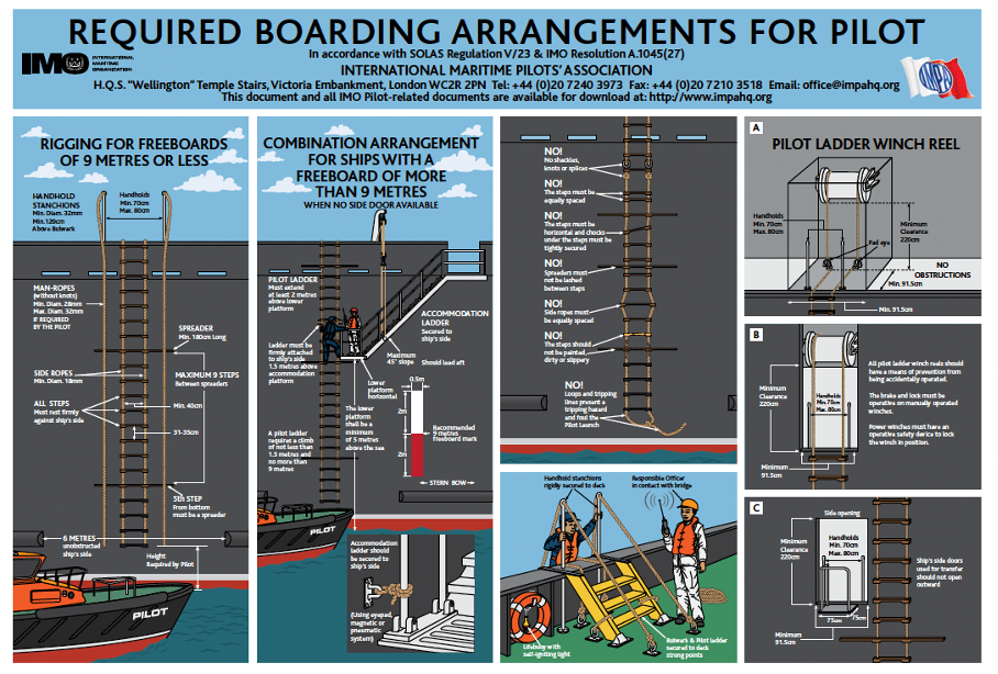
Fig 1: IMO / IMPA Wheelhouse poster (IMO & IMPA, 2018)
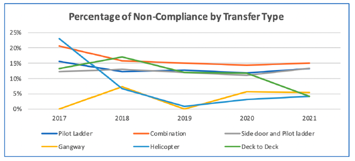
Whilst a lot has been described in detail in the above “Solas instruments”, the actual securing of the pilot ladder is not described at all. As a result of this, many methods of securing are in use today. Recent research into the use of pilot ladders has shown that on many occasions the method of securing onboard was either of insufficient strength or damaging to the integrity of the pilot ladder itself. (Evans, 2020)
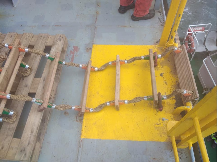
Fig 2: Using D-Schackles will damage the pilot ladder (Source: facebook group #dangerousladders)
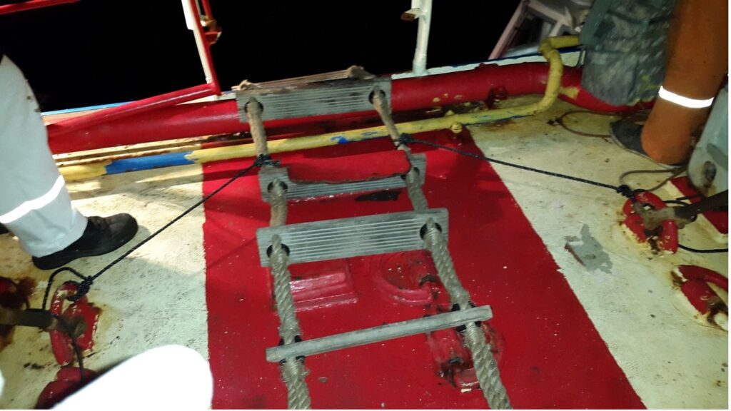
Fig 3: The shoestring method of securing (Source: facebook group #dangerousladders)
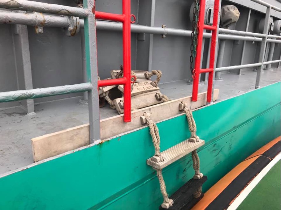
Fig 4: Using the spreader as a securing device (Source: facebook group #dangerousladders)
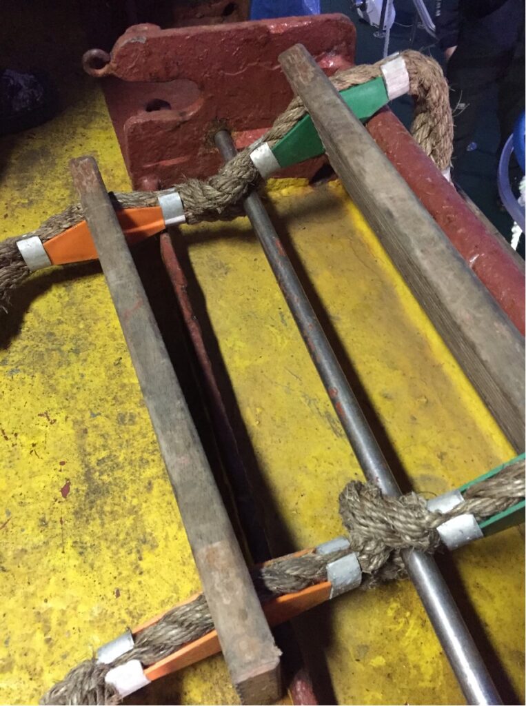
Fig 5: A steel bar used for securing the pilot ladder (Source: facebook group #dangerousladders)
The aim of the project was to design an innovative solution for the problem that has been defined as “There is no standard way of securing a pilot ladder at intermediate length that is easy to use, strong enough and not damaging to the structural integrity of the pilot ladder”.
Methodology
The term “innovation” in this respect not only means “inventing something new”. Many times, innovations come by using technical concepts from other fields of work. To this project the MIT 10 step design process (MIT Professional Education, 2019) was used. This step-by step approach ensures the designer(s) follow a structured plan while designing a technical innovation.

Fig 6: The MIT 10 Step Design Process
The methodology used does not guarantee a successful end product the first time. After verification when the performance of the product does not meet the pre-defined specifications, a redesign process may be required to optimize the design of the product. Hence the circle shape in the above picture.
The Research Phase
During the research phase, one client and four stakeholders were identified. PTR Holland, one of the largest suppliers of pilot ladders in the world acted as client. At the same time, Bart Kerklaan, a Rotterdam Maritime Pilot, Stolt Tankers, Lloyds Register and Vuyck Engineering acted as stakeholders. Interviews were held with all five parties to identify the user needs for the technical solution that was to solve the problem identified. From this, a seat of user requirements was obtained. These user requirements were translated to a set of design criteria.

Table 1: Program of Requirements
Using the design criteria and the user needs, a matrix was formed to determine the program of requirements. In this matrix a weighted assessment was given to each of the design criteria, to prioritize their importance for use in the design process.
The Design Process
The securing of the pilot ladder at intermediate length can be divided into 3 parts: (1) The securing (strong) points on deck, (2) The connection between the strong point and the ladder, and (3) The securing device of the ladder. The first two are very much dependent on the layout of the ship and can be solved by using existing shackles and strops or chains which are already in place.
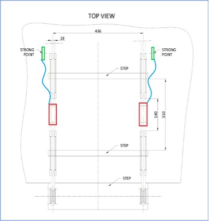
Fig 7: The 3 components of the pilot ladder securing
It was decided to focus the attention to the securing device at the side ropes of the pilot ladder. The securing device of the pilot ladder (3) was the real challenge of the project. The device had to transfer the forces from the strong point via ropes, strops, or chains on deck to the side ropes of the pilot ladder, using an existing pilot ladder. This meant in effect that no alterations could be made to the design of the pilot ladder. Also, the side ropes could not be damaged in any way using the securing device.
The next phase of the design process uses a creative exploration phase in which different ideas were used to approach the problem. In this case, various securing techniques from the yachting, mountaineering and marine industry were explored. In the end, three possible solutions were identified that could possibly solve the problem at hand. These solutions were evaluated in the framework of the design criteria. A morphological overview was used to determine which of the three solutions was the best option for the final design concept.
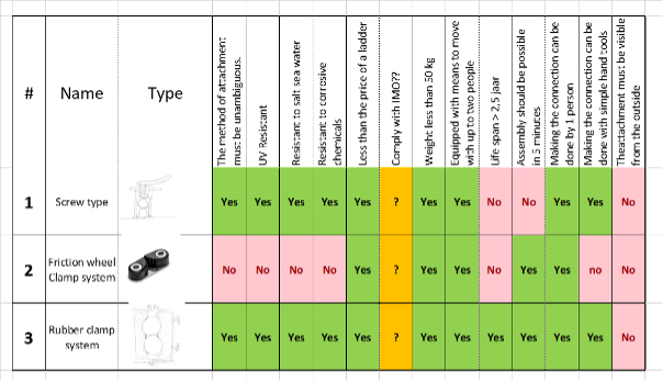
Table 2: Morphological overview of design concepts
After the evaluation of the outcome of this process, it was decided to design a steel clamp with rubber inserts for the securing to the side ropes of the pilot ladder. For economic reasons, the prototype was to be manufactured from mild steel materials. A set of CAD drawings was made up for the construction of the securing device.
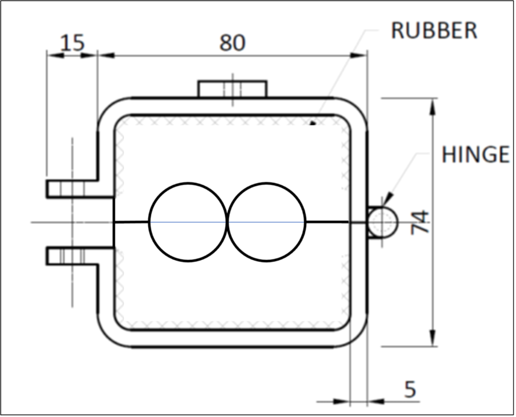
Figure 8a: Design of the securing device
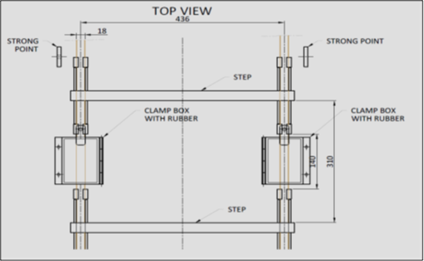
Figure 8b: Design of the securing device
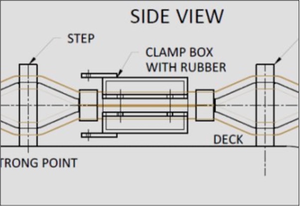
Figure 8c: Design of the securing device
The device was manufactured at Rotterdam Shipyard of the Rotterdam Boatmen Association KRVE. When it was delivered, two methods of securing were added to the device, one with polypropylene wingnuts, one with mild steel wingnuts. The latter one proved the most effective for the securing of the device to the pilot ladder side ropes. The prototype was fitted with a soft rubber compound which is commonly used for the watertight securing of doors and hatches onboard ships.
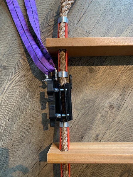
Figure 9a: Securing device in place
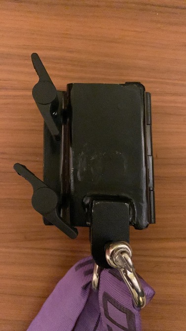
Figure 9b: Securing device with polypropylene handwheels
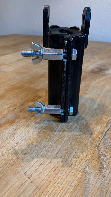
Figure 9c: Securing device with mild steel wingnuts
Verification
The final part of the design process was the verification. For this purpose, first all four stakeholders were informed about the outcome of the design phase and the details of the prototype. Valuable feedback was received from all stakeholders involved.
The second part of the verification was the strength testing of the securing device on the side ropes of the ladder. The dimensions of the device are such that at no point the device touches the clamps of the chocks of the pilot ladder steps. This is done to ensure no improper pressure is applied to the clamps of the ladder, which are not designed for that. The purpose of the strength test therefore was to determine the weight at which the device started to slip along the manila side ropes. For this purpose, the pilot ladder testing facility at PTR Holland was used.
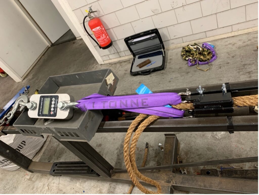
Figure 10: Test setup
During the test it was determined that the securing device could hold a weight of up to 290 kgs before it started to slip along the side ropes. No destructive test was performed on the securing device in combination with a pilot ladder. After the test, no visible damage to the side ropes was observed. When a load was applied to the ropes, it was very clear that the diameter of the side ropes decreased, which may have been a factor to the holding capability of the securing device.
Conclusions: Room for improvement
- The principle of a clamp-type of securing device is a feasible solution to secure a pilot ladder at intermediate length.
- The materials used should be changed to stainless steel for the outer shell to make it resistant to corrosion by salt and chemicals.
- More research into the type of rubber compound is required to improve the holding power of the securing device, and to make it resistant to chemicals and salt.
- More research into the optimum shape of the inner rubber lining is required to improve the lining design.
- A more user-friendly securing mechanism should be added to the design. In the respect the old fashioned “dog” screwing device must be considered.
- The weight of a typical 9 meters long ladder is 90 kgs. The average weight op a person is 100 kgs. In that respect a total holding power of 580 kgs is sufficient to carry the weight of both.
- No specification was given as to the minimum holding force of the securing device, let alone a Minimum Breaking Load (MBL) or a Working Load Limit (WLL) of the securing method and/or the ladder. When posing a risk to a person’s life, a safety factor of 10:1 is used to calculate the MBL. If the WLL required is 250 kgs, the MBL should be at least 2500 kgs.
Re-designing of the prototype
Designing a technical innovation is an iterative process. After the first verification, the designer may have to go back to the drawing board, using the results of the verification tests and the feedback from stakeholders and users. In this case, the outcome of the process so far has been presented to the client, who can then decide if further optimization is required and feasible, along the lines as described before.
Afterword
There is a lot that can be done to improve the safety of the transfer op personnel at sea by means of pilot ladders.
The design of the today’s pilot ladders in use does not allow for an easy fix to the project’s problem statement. In this respect one recommendation would be to redesign the pilot ladder altogether, to have a securing mechanism incorporated in the design.
The authors would like to thank PTR Holland, Stolt Tankers, Lloyds Register, Capt. Bart Kerklaan, Vuyck Engineering and Shipyard Rotterdam (KRVE) for participating in this project.
References
Pictures 2, 3, 4 and 5: from facebook group #dangerousladders
Evans, T. (2020). Strength of pilot ladders and intermediate securing of pilot ladders. (). Auckland, NZ: Troy Evans.
An investigation into actual strength of ladders and intermediate securing methods used.
IMO, & IMPA. (2018). Poster required boarding arrangements for pilot.(2) https://www.impahq.org/admin/resources/finalimpapladderposter.pdf
MIT Professional Education. (2019). The 10 steps to design thinking. professional.mit.edu. https://professional.mit.edu/news/articles/10-steps-design-thinking