Performance Standards for PTA’s Part A: – Design, Manufacture and Construction
4.1 The steps of the pilot ladders shall comply with the following requirements:
.1 if made of hardwood, they shall be made in one piece, free of any knots, wood shall not be treated or coated with paint, varnish or other coatings;
.2 if made of material other than hardwood, they shall be made from resilient plastic or rubber of equivalent strength, stiffness and durability;
.3 the four lowest steps shall be of rubber of sufficient strength and stiffness or other equivalent material;
.4 they shall have an efficient non-slip surface;
.5 they shall be long enough to accommodate a distance between the inner surface of the side ropes of not less than 400 mm, and shall be 115 mm in width and 25 mm in depth, excluding any non-slip device or grooving;
.6 they shall be equally spaced not less than 310 mm and not more than 350 mm apart measured from the top of each step or spreader step; and
.7 they shall be secured in such a manner that each will remain horizontal.

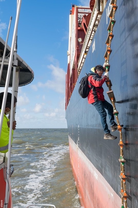
A bad pilot ladder, with worn-out steps and side ropes is not a good welcome sign for a pilot onboard a ship. It is easy to inspect the steps every time the ladder is used. Make sure the steps are in good shape, and clean, ready to use.
When markings are used, they should not be painted on the ladder’s steps, paint and varnish make the ladder slippery and therefore dangerous.
Compliance with the requirements in article 4.1 are the responsibility of the manufacturer. Any alterations, such as painting, marking, or other modification by ship’s crew is not allowed anymore under the new regulations.
4.2 Pilot ladders with more than five steps shall have spreader steps complying with paragraph 4.1 and each spreader step shall be not less than 1.8 m in length. The lowest spreader step shall be the fifth step from the bottom of the ladder and additional spreader steps shall be provided at such intervals as will prevent the pilot ladder from twisting conforming to standards accepted by the Organization (2).
(2) Refer to the recommendations by the International Organization for Standardization, in particular publication ISO 799-1:2019 Ships and marine technology – Pilot ladders – Design and specification.

A spreader step is a longer step, usually made of rubber or similar durable material, inserted at regular intervals in a pilot ladder. It spans a greater width than standard steps — at least 1.8 metres long — and serves a very specific safety purpose.
The primary function of the spreader step is to prevent the pilot ladder from twisting, especially when suspended freely from the ship’s side. Twisting ladders can create unstable footing, increase the risk of the pilot falling and obstruct safe boarding from a moving pilot boat.
By keeping the side ropes apart, the spreader ensures the ladder hangs straight and stable, making it safe to use under various sea conditions.
The first spreader must be positioned as the fifth step from the bottom. Additional spreaders must be added further up the ladder at intervals that prevent twisting. There is no maximum number, but they must be placed as needed to maintain stability.
This regulation makes a footnote reference to ISO standard 799-1:2019, titled “Ships and marine technology – Pilot ladders – Design and specification”. This ISO standard provides detailed technical specifications, including materials, construction methods, testing procedures and recommended spreader intervals and positioning.
By referencing ISO 799-1, the regulation acknowledges a globally recognized benchmark for quality and safety in pilot ladder design. The reference to ISO 799-1:2019 is not a legal obligation, but rather a recognized standard “accepted by the Organization” (IMO). In practice, SOLAS Regulation V/23 and the performance standards are mandatory; ISO 799-1 is used as a guidance document to meet those mandatory requirements.
Flag States, classification societies, and manufacturers often adopt ISO 799 as the technical basis for compliance. So while it’s not formally binding, adherence to ISO 799 is strongly expected and often necessary to demonstrate compliance.
4.3 Permanent measuring marking shall be provided at a regular interval of every three steps (approximately every 1 m) throughout the length of the pilot ladder consistent with ladder design, use and maintenance in order to facilitate the rigging of the ladder to the required height.

Pilot ladders must have permanent markings every one metre, usually every three steps. These markings may be printed on the steps, shown with a label or tag, or engraved. They must be strong, easy to read, and stay visible for the entire life of the ladder.
These markings are useful for both pilots and ship’s crew, helping them make sure the ladder is rigged to the right height — safely and correctly.
For pilots: The markings help them check the ladder height from the pilot boat before climbing.
For crew: The markings make it easy to rig the ladder to the exact height the pilot has requested, with no guesswork.
To know how long the ladder should be, the crew can calculate the freeboard (the height of the ship’s deck above the water) by subtracting the ship’s draught from its depth at the boarding point.
If the pilot requests a specific height of the ladder above the water, the ladder length can be calculated as:
Ladder Length = Freeboard – Requested Height
These markings improve safety. When the needed ladder length is known in advance, rigging becomes fast and accurate. The deck crew doesn’t have to guess — they can rig it correctly the first time.
4.4 Pilot ladders shall be permanently marked by the manufacturer with at least the following information on the underside of the uppermost step and the lowermost spreader step:
- the name of the manufacturer;
- an equipment serial number or other means of unique identification which the manufacturer shall be able to validate;
- date of manufacture; and
- name and details of the approving authority.
To ensure that only approved and traceable pilot ladders are used, each ladder must be permanently marked by the manufacturer. These markings must appear in two locations: On the underside of the uppermost step, and on the underside of the lowest spreader step
These markings must include:
- The name of the manufacturer, so that the ladder’s origin is clearly identified
- A serial number or unique ID, this allows the manufacturer to confirm that the ladder is authentic and traceable back to their production records
- The date of manufacture, this is crucial for checking whether the ladder is still within its approved service life (maximum 36 months as per performance standards)
- The name and details of the approving authority; The authority that certified the ladder as compliant with SOLAS and the IMO performance standards
These markings are not optional — they are a requirement under SOLAS and must be checked before use.
- Ladders without these markings must not be used
- The markings allow surveyors, pilots, and ship crews to instantly verify if a ladder is approved, compliant, and still within its valid lifespan
- If a ladder cannot be traced or verified, it is considered unsafe and non-compliant
Markings are a key part of a broader effort to eliminate counterfeit and unsafe ladders from use in the industry.
4.5 Pilot ladders shall be of a single length capable of reaching the surface of the water from the point of access or, where a combination arrangement is used, from the platform of the combination arrangement, in all seagoing conditions of draught and trim and the specific condition of an adverse list of 15° in the lightest seagoing condition.
This regulation ensures that the pilot ladder always reaches the water — no matter how the ship is loaded or positioned. It removes any guesswork: the ladder must always be long enough, for every voyage and condition.
The ladder must be: one continuous length (not tied together in sections), and long enough to reach from the point of access on the ship, or the platform of an accommodation ladder (if a combination arrangement is used).
It applies to all seagoing conditions, from ballast to full load, with any trim (bow or stern down), even if the ship has an adverse list of up to 15 degrees.
4.6 The side ropes on each side of the pilot ladder should consist of a double length of uncovered rope not less than 20 mm and not more than 22 mm in diameter. The double length shall be made from a continuous length of rope with no joints having a breaking strength of at least 24 kN. The midpoint of the double length shall be located on a thimble. The ends of each side rope shall be properly finished.
Side ropes are the key structural element of a pilot ladder, running down both sides and bearing the full weight of the ladder and the person using it. To ensure safety and reliability, strict construction standards apply:
- The ropes must be uncovered — not coated or sheathed — to avoid trapping moisture, which could cause rot and weakening over time.
- They must be a double length, looping from a thimble (typically at the top) down both sides of the ladder. Ladders with a loop at the bottom no longer comply with these rules. The midpoint of the loop must rest over a metal thimble, which protects the rope from chafing at the top attachment point.
- The rope must have a diameter between 20 mm and 22 mm, be continuous (no knots or joints), and have a minimum breaking strength of 24 kN.
- With four side ropes in total, the combined breaking strength is 96 kN (9.6 tonnes). This accounts for extreme situations — such as a pilot tender pressing against or hanging on the ladder.
- Rope ends must be properly finished to prevent fraying and loss of strength.
These features ensure the ladder can withstand not only regular use but also emergency loads. The use of a continuous rope adds redundancy, while the ban on joints or splices removes common failure points.
4.7 Each side rope shall be mildew-resistant manila rope* or other material of equivalent strength, durability, elongation characteristics and grip which has been protected against actinic degradation.
* (Refer to the recommendations by the International Organization for Standardization, in particular publication ISO 1181:2004.)
The regulation explicitly states that the side ropes shall be made of mildew-resistant manila — a strong natural fibre known for its durability and grip. Manila rope is the benchmark material for pilot ladders and offers excellent resistance to abrasion, moisture, and handling stress.
This is an important point, because inferior materials like sisal are sometimes found on counterfeit ladders. Sisal lacks the strength, stretch control, and lifespan of manila, and is not compliant under SOLAS requirements.
Alternative materials are allowed, but only if they meet all of the following criteria, matching or exceeding manila rope in strength, durability (resistance to wear and damage over time), elongation characteristics (controlled stretch under load, without permanent deformation) and grip (safe to hold and non-slip under wet conditions). In addition, any alternative material must be protected against actinic degradation.
Actinic degradation refers to the breakdown of materials due to exposure to ultraviolet (UV) light, particularly sunlight. UV rays can weaken rope fibres, causing brittleness, loss of strength, and eventual failure — especially on ladders stored on deck or exposed during use.
To protect against actinic degradation, manufacturers typically apply UV-resistant coatings to synthetic ropes or treat natural fibres like manila during production to enhance resistance.
Recommend proper stowage: ladders must be kept in dry, shaded, and ventilated areas when not in use (as reinforced later in Part D of the standards)
The regulation refers to ISO 1181:2004, titled: “Fibre ropes — Manila and sisal — Specification.”; This ISO standard defines material properties, rope construction, diameter tolerances, breaking strength values and quality control testing for natural fibre ropes.
By referencing ISO 1181, the IMO ensures that only genuine manila rope of verified quality is used , certainly not visually similar but inferior substitutes like sisal.
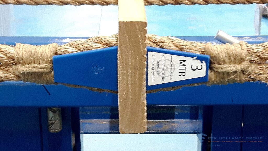
4.8 Each side ropes shall be secured together both above and below each step with an arrangement properly designed for this purpose. Where a seizing method* with step fixtures (chocks or wedges) is used, it shall hold each step horizontal in all planes at all times. Where a mechanical clamping device is used to secure each side rope together, it shall grip each side rope in the pair independently and with the same grip force. Any surface of a mechanical clamping device that pilots or other personnel may handle shall be suitable to be grasped by bare hands. The use of cable ties, u-clamps, worm driven clips as a means of securing steps within with side ropes is prohibited.
* Refer to the recommendations by the International Organization for Standardization, in particular publication ISO 799-1:2019 Ships and marine technology – Pilot ladders – Part 1: Design and specification.
In addition to requiring high-quality rope, the regulation also sets out how each step must be secured to the side ropes. This is a critical safety detail, as poor step attachments are a known cause of ladder failure.
The regulation allows two approved methods for securing steps:
- Seizing with step fixtures (e.g. chocks or wedges), this is the traditional method used on most manila rope ladders. Chocks or wedges are inserted between the side ropes and the step to hold the step firmly in place. These are then hand-seized, often using rope or whipping twine, to lock the step in position. The step must remain completely horizontal in all planes (side-to-side and front-to-back), and must not shift or tilt under load. This method is still permitted, but only if it is part of the manufacturer’s approved design, and if it is done exactly as intended by the ladder’s original construction.
- Mechanical clamping devices; Modern ladders may use mechanical clamps instead of traditional whippings. These devices must grip each side rope individually, not both together, to ensure that when one end of the clamping fails, the securing of the clamping fails totally. It should apply equal force to both ropes to keep the step level, being safe to handle with bare hands — no sharp edges, loose ends, or exposed metal. These clamps are precision-made and often factory-installed. Only clamps specifically designed and approved for pilot ladders may be used.
The regulation clearly prohibits common but unsafe DIY methods, including: Cable ties, U-bolts or U-clamps, and worm-driven hose clamps (jubilee clips). These items are not designed to handle the dynamic loads placed on a pilot ladder in use. They can shift, fail under strain, or damage the side ropes.
Correctly secured steps are essential to the structural integrity of the pilot ladder. Whether using traditional whippings or modern clamps, all attachments must be fit for purpose, compliant with the standard, and installed by design — not improvised.
Once again, reference is made to ISO 799-1 : 2019 for details of the securing of the steps.
